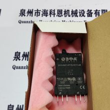
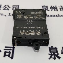
| 品牌:SCANA SKARPENORD | 型号:306.128.64 | 连接形式:焊接 |
| 材质:黄铜 | 公称通径:40mm | 3C阀门类别:工业 |
SCANA SKARPENORD截止阀306.128.64
泉州市海科恩机械设备有限公司
The level switch NRS 1-50 in conjunction with level electrodes NRG 16-50S/NRG 16-11S/NRG 16-38S and NRG
16-39S is approved for marine applications.
LVD (Low Voltage Directive) and EMC (Electromagnetic
Compatibility)
The level switch NRS 1-50 meets the requirements of the
Low Voltage Directive 2006/95/EC and the EMC Directive
2004/108/EC.
ATEX (Atmosphère Explosible)
According to the European Directive 94/9/EC the level
switch NRS 1-50 must not be used in potentially ex?plosive
areas.
Technical Data
Mains voltage
24 VDC +/– 20 %, 0.3 A or 100 – 240 VAC +10 / –15%,
47 – 63 Hz, 0.2 A
External fuse
M 0.5 A (semi-delay)
Power consumption
7 VA
Sensitivity of response (Electrical conductivity of water
at 25 °C)
> 0.5 ... <1000 μS/cm or
> ,10 ... <10000 μS/cm
Inputs:
Electrical connection of level electrode
1 input for level electrode NRG 1...-50, NRG 1...-11, NRG
16-36, screened control cable with four poles, minimum
conductor size 0.5 mm2, e. g. LiYCY 4 x 0.5 mm2.
Max. length 100 m with a conductivity > 10 ?S/cm at 25°C.
Max. length 30 m with a conductivity <10 ?S/cm at 25°C.
Stand-by input
1 volt-free input, 24 V DC, for monitoring the purging
and bypass time. Max. bypass time: 5 minutes.
Wiring: control cable 2 x 0.5 mm2.
Outputs:
Safety circuit
2 volt-free make contacts, 24 V DC - 250 V AC, max. 6 A
(resistive/inductive), contact material AgNi.
Delay of response: 3 seconds, 15 sec. for marine
applications.
Provide inductive loads with RC combinations according
to manufacturer&#39;s specification to ensure interference
suppression.
Signal output
2 volt-free outputs for instantaneous external signalling,
24 – 230 V AC/DC, max. 100 mA.
Wiring: control cable 2 x 0.5 mm2.
Indicators and adjustors
2 buttons for test and diagnosis, 4 red/green LEDs for
indicating the operating mode and alarm.
6 red LEDs for fault diagnosis.
Housing
Housing material: base: polycarbonate, black; front: polycarbonate, grey. Terminal strips separately detachable
Fixing of housing: Mounting clip on supporting rail
TH 35, EN 60715.
Electrical safety
Degree of contamination: 2, overvoltage category III to
EN 61010-01.
Dimensions
Wiring diagram
100
74
120
16 27
1 2 3 4 5 6 7 8
17 18 19 20 21 22 23 24
9
25
10
26
11 12
28
13
29
14
30
15
NRG 1...-50
NRG 16-36
L
M 0,***
(+)
+
(-)
-
N
N L N L
1
1 2
2
4
3
3
+ –
Key
8 Mains supply
9 Signal output 1 / 2 for external alarm
24-230 V AC/DC 100 mA
0 Safety circuit, external input and output
Fuse 2A or 1A, slow-blow (TRD 604, 72 hours)
a Wire link, on site, when used as water level
limiter acc. to TRD, EN 12952 / EN 12953
b Stand-by input 1, 24 V DC,
for connecting the logic unit SRL 6-50
c Level electrode NRG 1...-50, NRG 1...-11,
NRG 16-36
Protection
Housing: IP 40 to EN 60529
Terminal strip: IP 20 to EN 60529
Weight
approx. 0.5 kg
Further conditions:
Ambient temperature
when system is switched on: 0° ... 55°C,
during operation: –10 ... 55°C
Transport temperature
–20 ... +80°C (<100 hours),
defrosting time of the de-energized equipment before it
can be put into operation: 24 hours.
Storage temperature
–20 ... +70°C,
defrosting time of the de-energized equipment before it